2D线段操作
Line在Inspector面板中目前只适用于2D点,但是你可以使用LineMaker工具来做一些3D点编辑,基于现有的网格。
参数
Style 线条样式
Width线宽- 至少是1
Cap Length线段末端的封头长度

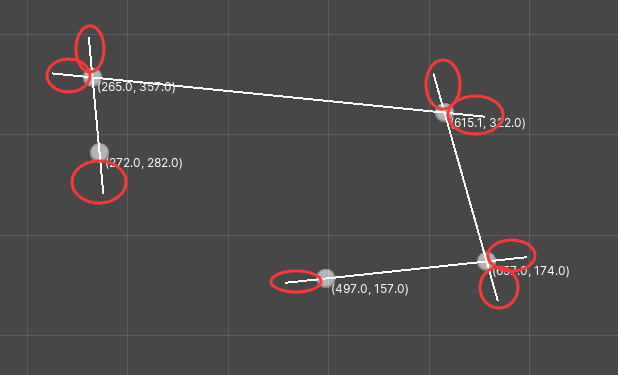
红圈就是Cap Length属性设置为40的效果
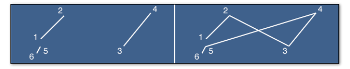
Color线条颜色LineType线条类型Continuous连续的- 连续的线是由所有的点连接而成的
- 任何线段的第二个点总是下一个线段的第一个点。
Discrete不连续的 (默认)- 必须是偶数长度
- 不能使用
Join连接 - 每两点用单独的线段构成不连续的线
Points点- 点只是画出实际的点,而不是线段
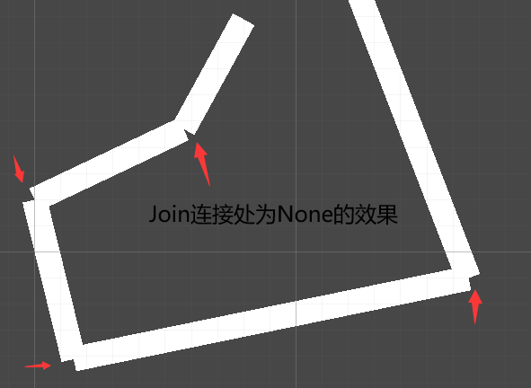
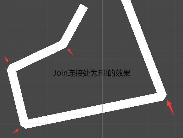
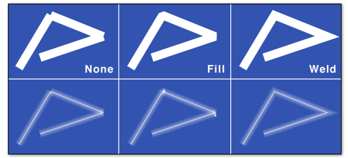
Join连接None无 (默认值)Fill填充- Fill用粗线填充可见的空隙
Weld焊接- 移动线段中的顶点以将它们焊接在一起。
如果第一个点和最后一个点是相同的话 Joins.Fill 和 Joins.Weld 会连接它们.

maxWeldDistance焊接线段时最长的距离- 关于
Join.Weld, 如果两个线段趋于平行,则尖角会很长,为了解决这个情况,使用maxWeldDistance
- 关于

默认情况下,这个距离是矢量线创建时像素宽度的两倍。因此,例如,像素宽度为20的直线,其默认maxWeldDistance为40。这可以改变后,在任何时候的行创建
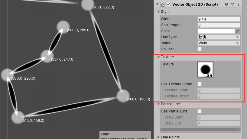
Texture 线条材质
默认情况下, 纹理沿着每个线段的长度进行拉伸.
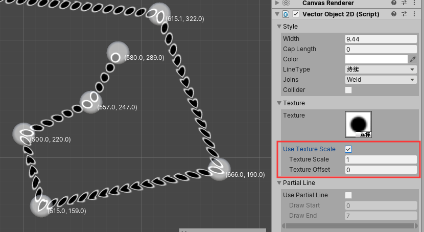
如果你使用Texture Scale,纹理将被均匀缩放。这要求纹理使用 Repeat 的模式(wrap mode),而不是 Clamp。
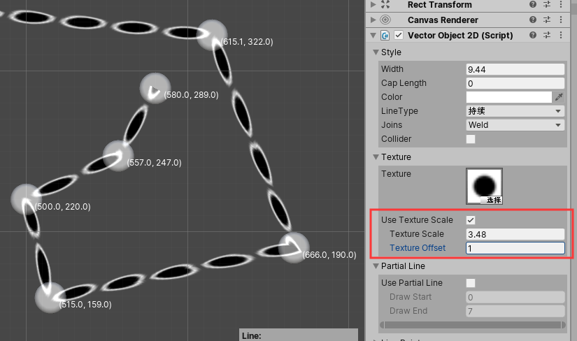
Texture Scale纹理缩放数字可以用来拉伸一个纹理的相对数量,使它重复。Texture Offset纹理偏移量将用一个相对量来偏移纹理
ContinuousTexture
如果您在您的line上使用纹理,纹理的默认行为是对每个线段重复一次。通过设置continuousTexture为真,你可以使纹理延伸整个长度的线。

EndPointsUpdate
允许您指定在调用Draw或Draw3D时,从末端实际更新多少个点。这使得Vectrosity可以跳过其余点的计算,从而提高性能。
// 只重绘最后2个点
myLine.endPointsUpdate = 2;
Layer
如果你想改变线条的GameObject层(用于相机筛选蒙版),
// 这与layers排序不同;使用 VectorLine.drawDepth用于线分类的绘制深度
myLine.layer = LayerMask.NameToLayer ("TransparentFX");
Partial Line 部分线
可以控制显示第几个点到第几个点的线段显示, 其余不显示.
Draw StartDraw End

只绘制前4段线段.
Line Points 线段上的点
一条Line由多个segments组成,

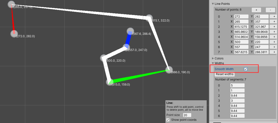
勾选Smooth Width之后的效果
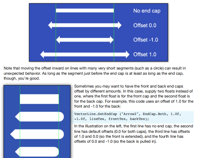
End cap
// 创建一个封头
VectorLine.SetEndCap ("Arrow2", EndCap.Mirror, -1.0f, lineTex, frontTex);
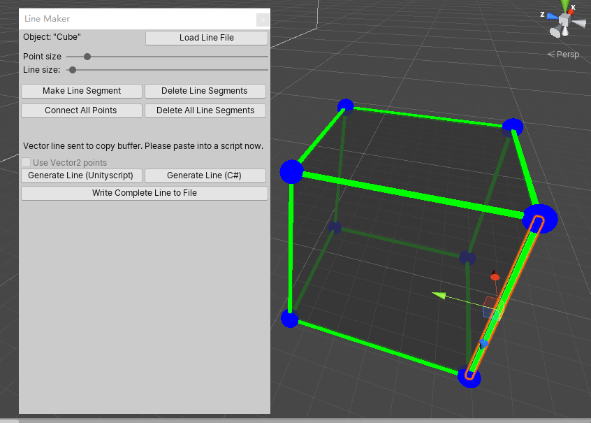
LineMaker可视化编辑3D线条
你可以使用LineMaker工具来做一些3D点编辑,基于现有的网格。
- 在你选择的3D应用程序中创建一个网格。理想情况下,这应该是合理的低多边形…LineMaker可能会有点慢与高多边形对象。拖动网格到你的场景。
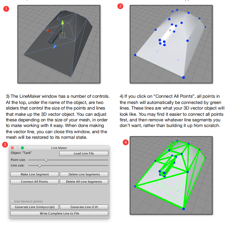
- 选中对象后,从Assets菜单中选择LineMaker。你的网格会变得透明,每个顶点上都有蓝点,并且会出现LineMaker窗口
- LineMaker窗口有许多控件。在顶部,在对象的名称下,是两个控制组成3D vector对象的点和线的大小的滑块。你可以根据你的网格大小来调整这些,以使工作更容易。当完成矢量线,你可以关闭这个窗口,网格将恢复到正常状态。
- 点击“连接所有点”,网格中的所有点都会自动用绿线连接。这些线就是你的3D向量对象的样子。您可能会发现,首先连接所有点,然后删除您不想要的线段比从头开始创建更容易。
- 选中对应边可以在上面显示出对应的段数Index
- 可以生成所有点对应的坐标点
代码中使用方法
// 画一条3个点的线段  形状 >
VectorLine.SetLine (Color.green, new Vector2(0, 0), new Vector2(Screen.width/2,
Screen.height/2), new Vector2(0, Screen.height) );

// 画一条射线, 长度为它方向的正前方5个单位处
// 以下2个区别在于显示会不会被对象阻挡
VectorLine.SetRay (Color.green, transform.position, transform.forward * 5.0f);
VectorLine.SetRay3D (Color.green, transform.position, transform.forward * 5.0f);

// 传入持续的时间, 之后自动删除,不然会永久存在
VectorLine.SetLine (Color.green, 4.0f, Vector2(0, 0), Vector2(250, 250));
VectorLine.SetRay (Color.green, 3.0f, transform.position, transform.forward * 5.0f);
注意: 在Update中使用这些命令时要小心!每次调用SetLine或SetRay时,它都会创建一个新line,与调试命令的默认行为不同,这些行会永久保留,除非您指定了持续时间。
如果你调用SetLine或SetRay的每一帧更新,你的场景将很快充满数百个重复的行对象。
您可以做的一件事是传入一个时间值。这将导致在给定的秒数内绘制这条线,然后删除它。
Draw()和Draw3D()都不会创建新的线条对象——相反,它们只会重新绘制现有的VectorLine对象,
- 每条Line使用不连续
discrete的类型时最多能有32765个点. - 每条Line使用连续
continuous的类型时最多能有16383个点.
// 如果你打算以后添加点,不想先提供任何点,你可以在行内声明一个空列表
var myLine = new VectorLine("Line", new List<Vector3>(), 2.0f);
利用Transform
使用它所附加到的任何对象的transform组件。您应该再次调用Draw来更新该line。你可以使用任何对象的Transform.
var myLine = new VectorLine("Line", linePoints, lineWidth);
myLine.drawTransform = transform;
myLine.Draw();

myLine.drawTransform = GameObject.Find("Some Object").transform;
如果您在每一帧中不断地用转换更新line,那么通常最好在LateUpdate中调用VectorLine.Draw。而不是Update,以确保更新是正确的,也就是说在transform移动之后进行更新。
删除
// 在销毁数组或列表的情况下,如果使用c#,则不需要“ref”。
VectorLine.Destroy (ref myLine);
VectorLine.Destroy (ref myLine, gameObject);
方法
Resize
调整一条线上的点数量
myLine.Resize (myLine.points2.Count + 50);
// 这个代码将使line有100个点,不管它目前有多少:
myLine.Resize (100);
// 您可以使用调整大小来删除点;你只要确保不低于0
myLine.Resize (myLine.points2.Count - 50);
GetSegmentNumber
返回一条Line上有多少段
// 返回49,25
var line1 = new VectorLine("Line1", new List.<Vector2>(50), 1.0f, LineType.Continuous);
var line2 = new VectorLine("Line2", new List.<Vector2>(50), 1.0f, LineType.Discrete);
Debug.Log (line1.GetSegmentNumber() + ", " + line2.GetSegmentNumber());
GetPoint01
它的工作原理与上面的GetPoint相同,只是它使用了0.0到1.0之间的标准化坐标表示距离。换句话说,是百分比而不是绝对值。如果您不关心这条线有多长,但是需要在这条线长度的某个百分比处有一个点,那么这是非常有用的。您可以在上面的脚本中使用这段代码来代替GetPoint,它将把GUIText定位在该行的中间位置
BytesToVector2Array and BytesToVector3Array
在代码中指定line points的另一种方法是使用包含Vector2或Vector3数组数据的TextAsset文件作为二进制数据。您可以使用LineMaker编辑器脚本创建这些文件。您可以为线条创建特定的形状,并将它们作为资产存储在Unity项目中,并像往常一样使用拖放。然后使用 BytesToVector2List 或者BytesToVector3List 将这些资产分别转换为Vector2表或Vector3表。
如果您有复杂的预先制作的形状,而另一种选择是Vector2或Vector3的长字符串,那么这是非常有用的数据。它还允许灵活地连接Unity检查器中的资产,而不是将数据硬编码到脚本中.
使用这些函数,首先需要一个TextAsset变量。然后将TextAsset中的字节传递到函数中,函数将其转换为适当的数组:
public TextAsset lineData; // C#
void Start () {
var linePoints = VectorLine.BytesToVector2List (lineData.bytes);
var line = new VectorLine("Vector Shape", linePoints, 2.0f);
line.Draw();
}
VectrosityDemos包中的_Simple3DObject场景就是这样一个例子。在多维数据集对象上,您可以使用Simple3D脚本(它将向量多维数据硬编码到脚本中)或Simple3D 2脚本(使用CubeVector TextAsset文件)。可以尝试从。中拖动不同的文件矢量文件夹到VectorCube槽,以获得不同的形状。
Selected
如果您想确切地知道所选择的线段(或点)是什么,您可以传入一个整数变量,该变量将在调用selected后包含线段或点索引。如果Selected返回false,则索引将包含-1 。例如:
if (line.Selected (Input.mousePosition), out index) ...;
还可以传入一个额外的整数参数,该参数实际上是为所选函数的目的将行宽扩展了那么多像素。这可以使单击行(特别是细行)变得更容易,因为输入不必精确地超过行。注意,即使您不打算使用索引,在使用额外的距离参数时也需要索引参数。例如,这将把一行的选择区域扩展10个像素:
if (line.Selected (Input.mousePosition, 10, index)) {
Debug.Log ("Selected!")
}
在某些情况下,您可能希望在线段的末端以及宽度上添加额外的选择空间。
为此,在第一个整数之后添加另一个整数;这将增加10像素的宽度和2像素的长度
if (line.Selected (Input.mousePosition, 10, 2, index));
请注意,默认情况下Selected使用SetCamera3D设置的相机,或者标记的第一个相机
如果没有使用SetCamera3D,则使用“MainCamera”。你可以提供一个不同的相机,如果需要,使用任何选择的超载:
if (line.Selected (Input.mousePosition), index, myCamera);
绘制形状的方法
MakeRect
function MakeRect (
    rect  : Rect,
    index : int = 0
    ) : void
在VectorLine中创建一个矩形。用VectorLine.points2 或 VectorLine.points3。
- 如果使用
Vector2,则提供的rect位于屏幕空间像素中, - 如果使用Vector3,则位于世界空间坐标中。
默认情况下,可选索引为0,但它可以是任何内容,只要rect适合VectorLine.points2或VectorLine.points3。这允许在同一行中创建多个矩形,因为用于创建矩形的点从索引定义的值开始。VectorLine.points2的长度或VectorLine.points3如果该行创建为连续行,则必须至少为5;如果该行创建为离散线需要至少8个点在Vector3列表中。
这是为了快速设置正方形或矩形,因为这是一个非常常见的事情来做的线条绘制(想想选择框之类的事情)。您可以通过提供一个Rect或两个描述左下角和右上角(坐标以屏幕像素为单位)的vector2来做到这一点。这适用于连续或离散的线,
- 在连续的线中,你需要至少5个点在Vector3列表中,
- 在离散的线中,你需要至少8个点在Vector3列表中,
myLine.MakeRect (Rect, index);

var squareLine = new VectorLine ("Square", new List.<Vector2>(8), 1.0f);
squareLine.MakeRect (new Rect(300, 200, 100, 100));
squareLine.Draw();

// 选择框的写法, index默认为0
selectionLine.MakeRect (originalPos, Input.mousePosition);
默认情况下, 矩形的绘制时从Vector3列表中的索引0处开始(选之后8个点进行绘制). 你可以选择指定的index. 通过Index可以在一条Line上绘制任意多个矩形. 这个方法适合用于不连续的line. (如果有24个点,可以绘制3个.index:0,8,16)
MakeRoundedRect
圆角矩形.
- cornerRadius 圆角半径,
- cornerSegments 段数, 越多越平滑
myLine.MakeRoundedRect (Rect, cornerRadius, cornerSegments, index);
myLine.MakeRoundedRect (Vector2, Vector2, cornerRadius, cornerSegments, index);
在大多数情况下,您不需要确切地知道创建一个圆角矩形需要多少个点,因为如果行中的points2或points3列表中没有足够的点,则需要添加更多的点。但有时它也很有用,比如使用索引在单个矢量线中创建多个圆角矩形。
因此:圆角矩形使用的段数是4 * cornerSegments + 4.
如何转换成点取决于线的类型; 线型连续的,是segments + 1, 线型离散的,是 segments * 2
下面是一个制作圆角矩形的例子,圆角矩形从一个角的(50,50)开始,一直到另一个角的(45,250),所以它是400像素宽,200像素高,半径为15像素,每个角使用5个线段:
var rectLine = new VectorLine ("RoundRect", new List.<Vector2>(2), 2.0f);
rectLine.MakeRoundedRect (new Vector2(50, 50), new Vector2(450, 250), 15.0f, 5);
rectLine.Draw();
MakeCircle
您可以指定线段、原点、半径和线段数量,其中更多的线段可以形成光滑的圆。如果您只使用几个段,它可以用于形状,如八角形,甚至三角形,如果您只使用3段。您可以选择指定点旋转,这通常对设置低段形状的方向很有用(当使用大量段时,效果几乎是不可见的)。另外,与MakeRect和MakeRoundedRect一样,可以指定索引,这样就可以在一个VectorLine对象中创建多个圆。同样,这对于离散的线很有用,因为在一条连续的直线上的多个圆当然都是连接在一起的。
myLine.MakeCircle (origin, up, radius, segments, pointRotation, index);
// 注意,其中一些参数是可选的,并且具有默认值。至少,你只需要原点和半径:
myLine.MakeCircle (origin, radius);
在本例中,圆将使用VectorLine中的所有可用段,因此不必指定要使用的段数。
用于此矢量线的points2或points3列表的大小必须至少为连续线的段数加1,或为离散线的段数的两倍。例如,如果您使用30段连续的线,则点列表必须至少有31个元素。对于一条离散的线使用30段需要点列表中的60个元素.
“PointRotation”是可选的,默认值是0.0。它是一个浮点数,指定点绕圆顺时针旋转的角度。(负值表示逆时针方向。)这通常是有用的,使低段圆在一个期望的方向

“Index”也是可选的,默认值为0。它的用法与makerecting中的索引值一样。例如,一个包含120个条目的points2列表的离散线可能包含两个包含30个段的圆,一个在索引0处,另一个在索引60处。(记住,离散的直线需要两倍的点,因为圆中有段,每段用两个点。)
“Up”是一个可选指定的Up向量,它只有在您使用带有Vector3数组的MakeCircle时才有用。 默认情况下,在Vector3中绘制的圆是面向X/Y平面的。你可能更喜欢圆有不同的方向,比如X/Z平面,所以它们平行于“地面”。向上的向量是一个向量3,是一个根据圆指定向上的方向的方向。例如,要在X/Z平面上画一个圆,需要Y轴向上,所以可以使用Vector3(0,1,0)或Vector.up:
myLine.MakeCircle (Vector3.zero, Vector3.up, 15.0f);
MakeEllipse
这与MakeCircle几乎相同,只是使用了两个半径值而不是一个。
您可以指定x和y半径值,以生成不同宽度/高度的椭圆。MakeCircle实际上使用了这个例程,但是它为x和y都传递了一个半径值,完整的格式是:
myLine.MakeEllipse (origin, up, xRadius, yRadius, segments, pointRotation, index);
myLine.MakeEllipse (origin, xRadius, yRadius);
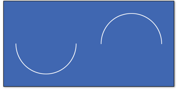
MakeArc
你可以用这个函数很容易地画出一个圆或椭圆的一部分。它与MakeEllipse非常相似,只是您可以用度数指定圆弧的起点和终点。
myLine.MakeArc (origin, up, xRadius, yRadius, startDegrees, endDegrees, segments, index);
// 至少,你需要定义原点、半径、起始度和结束度:
myLine.MakeArc (origin, xRadius, yRadius, startDegrees, endDegrees);
例如,这里有两个弧,其中第一个弧是用90表示起始度,用270表示结束度。第二个定义使用270作为开始,90作为结束。使用450也可以
(270 + 180)为结尾。
MakeCurve
这允许在现有的贝塞尔曲线的创建VectorLine对象。这些曲线由两个锚点和两个控制点构成。你可能已经了解了一般用法MakeRect /圈/椭圆部分。它的结果可能是这样的曲线,取决于锚点和控制点的位置:
myLine.MakeCurve (curvePoints, segments, index);
myLine.MakeCurve (anchor1, control1, anchor2, control2, segments, index);
在第一种情况下,curvePoints是一个由4个元素组成的Vector2或Vector3数组,其中元素0是第一个锚点,元素1是第一个控制点,元素2是第二个锚点,元素3是第二个控制点。在第二种情况下,锚点和控制点被写成单独的向量2或向量3。这些都使用屏幕像素作为坐标,或世界坐标的矢量3线。线段参数是int,其工作方式与MakeCircle/MakeEllipse类似:线段越多,曲线看起来就越平滑。同样,Vector2数组中的元素数应该是线段数加上连续线段数,或者是离散线段数的两倍。或者,您可以完全省略段,而MakeCurve将使用尽可能多的段来适应VectorLine,因此最短的形式是
myLine.MakeCurve (curvePoints);
MakeSpline
这有点类似于MakeCurve,因为它在现有矢量线中生成曲线。主要区别在于,您可以传入一个包含任意数量点的数组,MakeSpline将创建一条曲线,该曲线将穿过该数组中的所有点。(如果您熟悉Catmull Rom样条曲线,您可能已经猜到MakeSpline使用的是这种方法。)样条曲线可以是开放的,就像MakeCurve一样,也可以是闭合的循环。
在_Main相机对象上,您可以设置段的数量,以及切换曲线是否为闭合循环,以及是否使用直线或点。
myLine.MakeSpline (splinePoints, segments, index, loop);
// 实际上只需要第一个参数,所以最短的形式是:
myLine.MakeSpline (splinePoints);
“SplinePoints”是一个Vector2或Vector3数组,包含任意数量的元素。生成的曲线将直接通过所有提供的点,因此与MakeCurve中使用的bezier曲线不同,这里没有控制点。
“循环”是指样线条是开的形状还是闭的形状。默认情况下这是false,所以如果你想要一个闭合循环,你必须指定true。
MakeText
myLine.MakeText ("Vectrosity!", new Vector2(100, 100), 30.0f);
您可以在字符串中为新行使用“\n”。你不必担心文本需要多少行段……如果行点列表不够大,不能容纳所有的点,就需要调整大小。
位置是在屏幕空间坐标中的向量2线和世界坐标的向量3线,同样大小是像素的向量2线和世界单位的向量3线。默认情况下字符间距和行间距分别为1.0和1.5,但是您可以通过自己指定来覆盖它们:
myLine.MakeText ("Hello world!", new Vector2(100, 100), 30.0f, 0.8f, 1.2f);
您还可以通过添加“true”或“false”来指定文本是否应该以大写形式打印;默认情况下这是true
myLine.MakeText ("Hello world!", new Vector2(100, 100), 30.0f, false);
MakeWireframe 线框
这和你用LineMaker工具的效果是一样的,点击“连接所有点”按钮,但它在运行时与任意网格一起工作。如果网格中有任何使用四边形的网格,那么线就是由四边形构成的。
要使用它,首先设置一条线,然后调用VectorLine.MakeWireframe和网格制作线框。这条线必须使用 Vector3点,并且必须是一条离散的线。不管 Vector3有多大——如果需要的话,列表的大小会被调整,以适应网格的所有线段。对于下面的示例,您可以将脚本附加到一个对象上,为“myMesh”变量选择某种类型的网格,当运行时,网格将显示为一个线框。你可以把它和VectorManager功能。
var myMesh : Mesh;
function Start () {
var line = new VectorLine("Wireframe", new List.<Vector3>(), 1.0f, LineType.Discrete);
line.MakeWireframe (myMesh);
line.Draw();
}
MakeCube
function MakeCube (
      origin : Vector3,
      xSize  : float,
      ySize  : float,
      zSize  : float,
      index  : int = 0
      ) : void
在VectorLine中创建一个立方体。
VectorLine.points3(必须有至少24个点数)。VectorLine必须是LineType.Discrete。origin是立方体中心的世界空间坐标。xSize、ySize和zSize是浮点数,指示这些维度的立方体的大小。- 可选索引
index默认为0,尽管可以为任意值,只要VectorLine.points3的count至少为24加索引即可。
使用这个函数可以很容易地做出任意的立方体。与MakeWireframe一样,它需要一条由Vector3点构成的离散线。与MakeWireframe不同,列表的大小很重要——它必须包含至少24个点。当调用MakeCube,指定位置为Vector3, x、y、z维为3个浮动:
var line = new VectorLine(“Cube”, new List.<Vector3>(24), 2.0f);
line.MakeCube (Vector3(4, 0, 5), 3.0f, 4.5f, 3.0f);
line.Draw();
还可以指定绘制多维数据集的数组的索引号(缺省值为0)。您可以使用它在一个向量行中拥有多个多维数据集,或者将多维数据集与其他线段组合在一起。只需记住,多维数据集需要从指定索引中计算出24个点,因此,如果从索引24开始计算,那么数组的总大小至少需要为48。这将使两个嵌套的立方体在一个矢量线:
line.MakeCube (Vector3.zero, 1.0f, 1.0f, 1.0f);
line.MakeCube (Vector3.zero, 2.0f, 2.0f, 2.0f, 24);// index必须要有24个点
ObjectSetup
要将一个GameObject(游戏物体)转换成3D vector object(矢量对象),你应该先建立一个描述你想要的形状的Vector3数组或列表,然后使用这个数组创建一个VectorLine对象,然后,调用VectorManager.ObjectSetup, 传递了GameObject、VectorLine对象、它应该具有的可视性控制类型和亮度控制类型:
VectorManager.ObjectSetup (gameObject, vectorLine, visibility, brightness, makeBounds);
根据参数的不同,它会在运行时向GameObject添加一些脚本组件。然后你有一个3D向量对象它的行为就像GameObject(游戏物体)一样.
注意,从现在开始,一切都是完全自动化的。你所要做的就是像往常一样移动所提供的GameObject(游戏物体)。它可以在物理控制下或直接控制你喜欢的任何东西。你可以把它想象成一个标准的GameObject(游戏对象),渲染器被一个VectorLine对象代替。如果你不想要它,只要摧毁GameObject,矢量线也会被完全摧毁。不要使用VectorLine.Destroy。当游戏对象被销毁时,VectorManager将自动处理line销毁。如果你有多个GameObject(游戏对象)你想让它们成为VectorLine对象,那么每个GameObject(游戏对象)都应该调用ObjectSetup。
对于相同的行和对象,可以再次调用ObjectSetup;例如,您可以使用Visibility.Static,然后切换到 Visibility.Dynamic。
有几种类型的visibility控制:
Visibility.Dynamic:- 当GameObject(游戏物体)是可见的时候,3D矢量对象总是在每一帧被绘制,而当它没有被任何相机看到时,3D矢量对象就不会被绘制,就像普通的GameObject(游戏物体)一样。这省去了计算不在视图中的线的麻烦,并且是通过使用普通的GameObject的渲染器来完成的——如果你禁用了GameObject的渲染器,那么vector对象也将被禁用。用它来移动物体。
Visibility.Static:- 类似Dynamic的,仅在可见时绘制。与动态不同,它只在相机移动时绘制(相机不动,就不需要重新绘制). 另外,绘图例程要快一些,因为它没有考虑对象的Transform。你可以把它用在不动的物体上。例如,在坦克区域演示包中,坦克、飞碟和炮弹使用可见性。动态的,而障碍则利用可见性。注意,与其他可见性选项不同,每个对象使用的点列表将自动成为一个新的惟一列表。这是因为对象的转换信息被放入列表中。
Visibility.Always:- 三维向量对象将总是绘制每一帧,没有优化从动态或静态的。如果你有一个总是在摄像头前面的物体,你可以用这个。如果你使用的GameObject(游戏物体)有一个网格渲染器,你应该禁用它,如果你只想看到矢量对象而不是GameObject(游戏物体)。(这不适用于Visibility.Dynamic或Visibility.Static。)
Visibility.None:- 不添加任何VisibilityControl脚本。如果在此对象之前使用过任何其他可见性选项,则可见性脚本将被删除。通常没有太多理由使用这个,除非你自己用VectorLine更新line 用Draw3D().
有两种类型的亮度控制:
Brightness.Fog:- 这模拟了三维矢量对象的雾效果。你可以在 Tank Zone demo package,中看到这一点,在这里,物体在远处会变成黑色。对雾效果的控制已经完成
VectorManager.SetBrightnessParameters(见下文)。注意,只支持单行颜色;也就是说, VectorLine.color。使用SetColor或SetColors设置的任何线段颜色都将被忽略。
- 这模拟了三维矢量对象的雾效果。你可以在 Tank Zone demo package,中看到这一点,在这里,物体在远处会变成黑色。对雾效果的控制已经完成
Brightness.None:- 线段的颜色保持不变。如果ObjectSetup已与亮度一起使用。雾对于这个物体来说,以前的亮度。雾脚本将被删除。
MakeBounds:- 默认情况下这是true,因此只需要在您不想使用它时提供它。在这种情况下,你应该在结尾加上“false”:
VectorManager.ObjectSetup (gameObject, myLine, Visibility.Static, Brightness.Fog);
VectorManager.ObjectSetup (gameObject, myLine, Visibility.Always, Brightness.Fog, false);
What this does when true, is create an invisible bounds mesh for the GameObject that you’re using to control the vector object. Why would you want this? Well, remember Visibility.Dynamic and Visibility.Static, and how they optimize things by not updating lines when the objects aren’t visible—they do this by using OnBecameVisible and OnBecameInvisible. But these functions require mesh renderers to work. And you don’t actually want to see a mesh renderer, you just want to see the VectorLines.
The invisible bounds mesh solves this by creating a “bounding cube mesh” that actually only consists of eight vertices that make up the object bounding box, and no triangles. But this is good enough for Unity! Even though you can’t see this mesh, it still allows OnBecameVisible and OnBecameInvisible to work just fine.
This invisible bounds mesh is created automatically when you use Visibility.Dynamic or Visibility.Always. Whatever mesh renderer the GameObject might be using is replaced by the bounds mesh (don’t worry, not permanently — only at runtime). Note: as an optimization, only one bounds mesh is created per VectorLine name. So all VectorLines called “Enemy”, for example, will have the same bounds mesh. This means it’s highly recommended to use different names for different types of VectorLine objects, and not just call every line “X” or something. Of course, if you have a bunch of objects that all look alike, such as the tanks in the Tank Zone demo, it’s fine for them to use the same bounds mesh. So, why might you use false for makeBounds, anyway? You might if you’re using Visibility.Dynamic or Visibility.Always, and you actually don’t want the GameObject’s mesh to be replaced. For example, the Simple3D3 script in the VectrosityDemos package uses false for makeBounds, so that the cube mesh is still visible. This makes a solid-shaded cube with vector line highlights, for a nifty wireframe effect.
SetBrightnessParameters
当你使用Brightness.Fog时, 你需要一些方法来控制外观。有五个参数:最小亮度距离,最大亮度距离,levels,距离检查频率,雾色。
Total Fadeout Distance: The distance from the camera at which brightness will be faded out all the way. The default is 500. Anything beyond this distance will be drawn with only the fog color.
Full Brightness Distance: The distance from the camera at which brightness will be at the maximum. The
default is 250. Anything closer than this distance will be drawn at max brightness. Anything between the full brightness and total fadeout distances will be proportionally lerped between the line color and the fog color.
Levels: The number of brightness levels, with the default being 32. This simulates limited color precision, where there are visible “steps” between each level. For a smoother fade, use a higher number.
Distance Check Frequency: How often the brightness control routine is run on objects that use Brightness.Fog. The default is .2, which is 5 times per second. You might want this to run more often if you have more brightness levels, or fast-moving objects.
Fog Color: The color which objects fade to as they approach the maximum brightness distance. This is black by default. Usually you want this to be the same as the background color.
An example where the minimum brightness distance is 600, the max is 200, there are 64 brightness levels, the routine runs 10 times per second, and fades to a dark blue
VectorManager.SetBrightnessParameters (600.0, 200.0, 64, 0.1, Color(0, 0, 0.25));
GetBrightnessValue
If you are doing some effects where it would be useful to know what brightness a 3D vector object should be at a certain distance, then you can use VectorManager.GetBrightnessValue (Tank Zone uses it in a couple of places). If you pass in a Vector3 in world space, typically from a GameObject’s transform.position, it returns a value between 0.0 and 1.0, where 1.0 would be 100% brightness and 0.0 would be 0% brightness.
Debug.Log (VectorManager.GetBrightnessValue (transform.position));
Q&A
Q: I can’t see any lines!
A: If you’re supplying your own color, make sure the alpha value is non-zero, or else the line will be transparent.
If you’re using VectorManager for 3D shapes, be aware that the scene view camera can interfere with the
Visibility scripts. To avoid this, just make sure the scene view isn’t active when running. The easiest way to do
that is to use Maximize On Play.
If you’re using a line material that reacts to lighting, you should set the vector canvas to OverlayCamera. The
easiest way to do that is by using VectorLine.SetCanvasCamera with the appropriate camera.
Q: I get error messages when I try to import Vectrosity into my project.
A: Make sure you’re using Unity 5.2 or later, since Vectrosity 5 uses some features not available in earlier
versions of Unity. Also, make sure you haven’t imported both the Vectrosity .dll and the source code—you
can only import one or the other.
Q: How can I get the best speed?
A: Make sure you don’t recreate lines unnecessarily. Don’t destroy and remake lines every frame. For the
most part, you should only create lines once in Start or Awake, and then manipulate the lines by changing
already-existing points. For dynamic lines such as those used in touchscreen line-drawing routines, make
use of VectorLine.endPointsUpdate to update only the last part of the line as needed, rather than constantly
redrawing the entire line. See the DrawLinesTouch or DrawLinesMouse example scripts in the
VectrosityDemos package for examples of this.
For the absolute best speed, stick to Draw rather than Draw3D. Remember that Draw can still draw lines
made with Vector3 points, though they will be drawn on top of everything else. Only use Draw3D when the
line really has to be drawn “inside” the scene along with other objects. Also, continuous lines are a little more
efficient than discrete lines, so use continuous where possible, and if you’re drawing thick lines, use Joins.Fill
instead of Joins.Weld if it’s feasible.
Finally, only call Draw when you actually need to. For example, there’s no reason to put Draw in an Update
function if the line only changes occasionally. However, note that 3D lines do need to be updated whenever
the camera moves (unlike standard lines), so you can usually use Draw3DAuto for those.
Q: I get error messages when I try to build for mobile.
A: Make sure you haven’t included any scripts from Tank Zone. The Tank Zone demo scripts use dynamic
typing, which isn’t available for iOS or Android builds.
Q: I get an error when compiling for iOS.
A: Make sure the Vectrosity .dll in Unity is named “Vectrosity.dll” exactly; if it’s renamed it won’t work.
TIPS AND TROUBLESHOOTING 49
Q: I’m using VectorLine.rectTransform, and it’s messing up the lines.
A: In most cases you shouldn’t use rectTransform unless you have a very good understanding of how
Vectrosity works. Consider it an “advanced” feature, which can be used for optimization in certain
circumstances, but it’s usually not necessary, and most things in Vectrosity can be accomplished without
using it. Typically you would pass in the transform of an object using .drawTransform, and then manipulate
that transform, instead of using rectTransform.
Q: I get an error about an unknown identifier when I try to do anything.
A: Make sure you import the Vectrosity namespace in your scripts. That’s “import Vectrosity;” for Unityscript,
and “using Vectrosity;” for C#.
Q: My lines look weird and don’t seem to be facing the camera.
A: Vectrosity is probably using a different camera than the one you want. It can happen that you accidentally
have a duplicate camera somewhere, in which case getting rid of it will fix the problem (and make your
project run faster too). If you have a multi-camera setup and are using 3D lines, be sure to use
VectorLine.SetCamera3D with the correct camera.
Q: I tried using GetPoint but it’s not working right.
A: Make sure you call SetDistances first, before calling GetPoint, if you’ve changed the VectorLine.